I strongly recommend preparing and securing the support first. With the antenna attached, an unsecured setup can tip, loosen, or fall in the wind, potentially damaging the antenna. Before assembling the antenna, choose your spot, set up the tripod, and level it. Anchor the guy lines, raise the mast to your intended operating height within its limits, and adjust the cords with enough tension to steady it without overtightening. Final tensioning comes after the antenna is installed.
Buddipole offers an adapter pole for mounting the BuddiHEX on a third-party mast. I recommend getting it, but mine came with no instructions at all for attaching it to a third-party mast. I received no help with that fitting and had to work out the installation myself.
1. Prepare the support before the antenna
Set the tripod on firm ground with room for the beam’s roughly 22-foot turning diameter, the feedline, the guy lines, and people handling the antenna. Keep clear of overhead wires. Place the feet so they cannot slide or sink, especially on a hillside. For a one-person setup, I use sandbags to help steady the tripod while I work, particularly when there is some wind. The guy lines provide the main support; sandbags are an aid during setup, not a replacement for securing the guys.
Adjust height and spread separately
Lower leg latch: open the quick-release lever, slide that telescoping leg to the needed length, then close the lever fully. This changes the tripod head height and lets a foot meet uneven ground. Brace/rod latch: release the separate latch on the support brace that runs back toward the center mast; reposition the brace to change that leg’s angle and spread, then lock it again. On a hillside, each leg can be set independently to place its foot securely and keep the head level. Do not confuse this brace adjustment with the lower length latch.
After each adjustment, check that the foot is planted and each latch is fully locked. Read the built-in bubble level at the tripod head and adjust the legs until the mast support is level. Recheck it after fitting the mast and after applying guy-line tension.
The seven- and ten-meter MastWerks systems are supplied with guy hardware for two levels; the shorter four-meter version uses one level. The upper and lower guy rings provide attachment points at different heights. The line system ties those rings to anchors and lets you tension the mast without pulling it out of plumb. The shaped MastWerks tube resists rotation without relying on the collar locks, which secure the telescoping mast sections. The tripod’s crank drives a geared rotating system that turns smoothly and resists wind-driven rotation. Use the crank mounted on the side of the tripod to turn the antenna. Do not loosen the telescoping collars to rotate the antenna.
Prepare the supplied guying system

1 · Opposite facesStart with the plates facing in opposite directions, as shown.
2 · Align the slotsRotate both plates so their entry slots align, then slide them over the narrow side of the mast.
3 · Rotate backRotate the plates back into alignment, matching the profile shown.
4 · Snap togetherAlign the posts and holes, then snap it together.
Before installing the beam, identify the two triangular plate halves, line toggles, winders or tensioners, and supplied stakes or other approved anchors. Rotate the plate halves until their access openings point the same way, with one face up and the other down. The MastWerks mast is black, with a subtly asymmetric, oblong rounded-triangular profile that is slightly broader at the back and narrower at the front. Pass the narrow side through the aligned openings. Then rotate the plates back relative to each other. As the large outer holes line up, the raised posts should snap into the small receiving holes. The mast cross-section in the drawing is based on my description. The central raised lips form the rounded opening visible in my photos. Check the fit on the exact mast section before loading it. The seven-meter system uses upper and lower guying levels.

Pass the line once through the hole, then loop it back around itself for a second pass to secure the toggle. This helps keep the connection secure in windy conditions and during adjustment. I have had a single pass come loose even in lighter wind, especially when lowering, raising, or tightening the setup. There is nothing quite like having to lower the antenna again just to reconnect a guy line that has slipped free. Before raising it, check that the loop and toggle are seated securely and recheck them after adjustments.
Lay the lines toward their intended anchors while the mast is still low. Give each line a clear route that will not cross the tripod feet, feedline, or antenna as it turns. Seat each toggle fully in its plate hole, and check that the line is threaded and secured as intended. The lines stabilize the mast at their two heights; the anchors resist pull. They do not make an overloaded or incompatible support safe.
Extend the mast sections to your desired operating height, within the mast’s limits, and lightly tension the guy lines to their anchors. Leave enough clearance to walk around the setup. Do not overtighten the lines; use just enough tension to steady the antenna as you raise it to operating height.
For my seven-meter mast, I recommend leaving the topmost section fully retracted and extending the next section by no more than one-third. When I extend that second section farther, the antenna begins to lean in different directions even with the guy lines secured. Decide on this configuration before proceeding. You can also leave both top sections fully retracted for a more rigid setup.
Now lower the mast to its lowest position. With the support prepared, we can begin assembling the antenna itself.
2. Build the antenna low and in order
If you are under six feet tall, you may find it easier to assemble the antenna on the ground. I do not recommend the optional setup assist. In my experience, it adds expense and makes setup harder. Ground assembly is fine if it gives you better access. Otherwise, place the hub on the lowered mast and secure it before continuing.
Before opening the spreader arms, attach the coax connection unit to the top blue 20-meter connection point and connect the coax cable you plan to use. This will be the back of the antenna. Route the cable now while this area is easy to reach.
Join every spreader section completely

Take one spreader arm at a time. Unfold it, untangle its cords, and fully seat each ferrule joint so the sections meet with no gap. Move a wire clip aside if it hides a joint. Do not assume a connection is fully seated just because it feels right; visually inspect every joint before installing the arm. A clip can hide an incomplete joint, making it feel seated when it is not. That leaves the ferrule or spreader arm vulnerable to bending or damage.
I cannot stress this enough. One of my joints was only slightly short of fully closed. When I assembled the antenna, I permanently damaged the ferrule and had to buy a replacement.
Attach the six spreaders at the lower hub
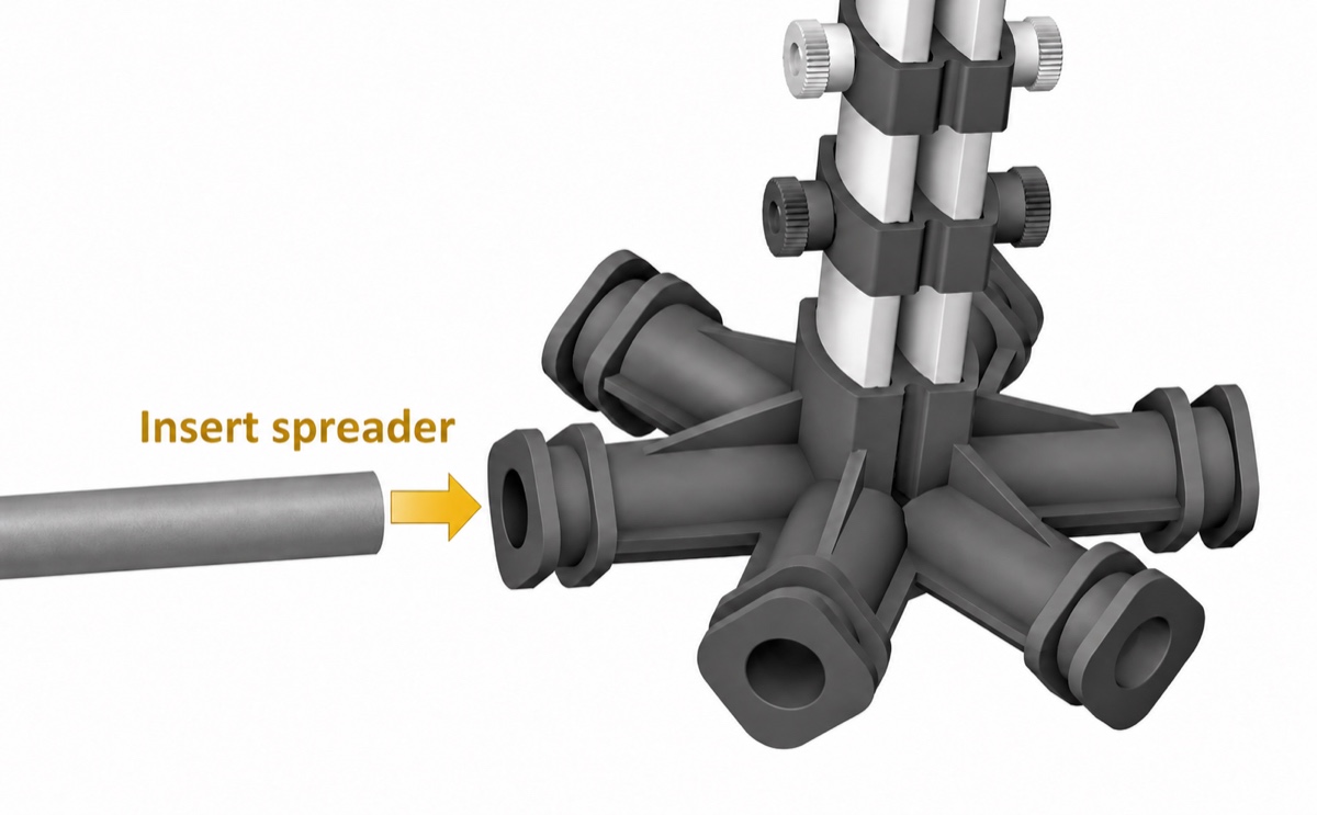
Insert each of the six spreader arms completely into its lower hub socket. This is important: a partially inserted arm can break or damage the antenna. Add each opposing arm rather than loading one side all at once, keeping the frame balanced as you assemble it. Confirm that every spreader is fully seated, the wire clip openings face downward toward the ground, and all connections are secure.
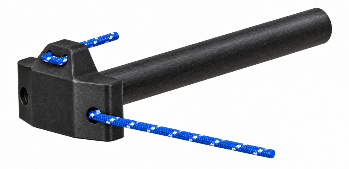
Orient each end fitting with its raised tab pointing straight up. Arrange the support cords so one runs to the right and the other runs toward the hub, as shown in the figure above.
Lock the center support toggle and join the tips
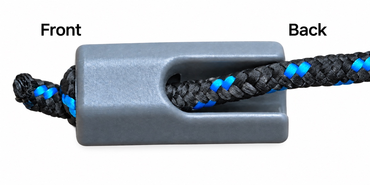
Start with the top cord and pull it upward toward the hub. The spreader arm will bend gently upward.
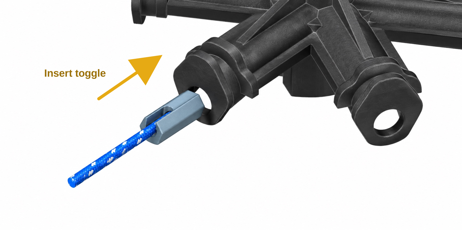
Hold the toggle at the back, pull on the cord, and hold it in position with your thumb. Insert the toggle completely through the hub opening. Once it is fully through, it opens and locks in place. Check that it is securely engaged before releasing the cord. Move to the opposite spreader and repeat, alternating between opposing sides to keep the frame balanced.
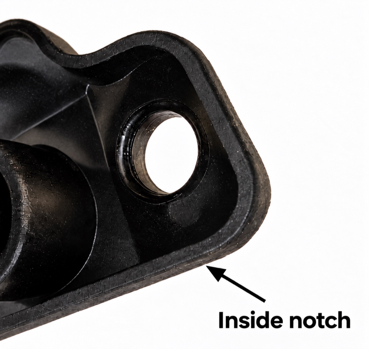
Start with the perimeter cords and, working counterclockwise, connect each one to the neighboring spreader. Insert the toggle through each end fitting from the outside toward the inside, then lock it in place. Notice the inside notch shown above: the toggle seats and locks into that notch on the inside of the spreader’s end fitting. Continue all the way around until the structure is complete.
3. Install the band wires from the outside inward
Begin with the blue 20-meter wire. Connect it at the top hub on the side opposite the coax cable, then run it to the first blue wire clip.

Keeping light tension on the wire, slide it into the retaining notch inside the blue clip. Keep the wire on the outside, or underside, of the antenna’s umbrella-shaped frame. Work counterclockwise around the spreaders, fitting the wire into each blue clip until you reach the last one.
After clipping the wire into the last clip, bring its free end back toward the hub. Connect it to the terminal opposite your first connection and tighten the connection. The wire should form a V, with the V opening opposite the coax connection at the back of the antenna. Check again that the wire runs along the outside of the frame.
Repeat the same procedure for each band, working from the outside inward and using the matching colored clips. The band order is:
- 20 meters — blue.
- 17 meters — green.
- 15 meters — red.
- 12 meters — yellow.
- 10 meters — light gray.
- 6 meters — black or dark gray.
Continue until all six band wires are installed. Check that each wire is seated in its clips and runs outside the umbrella-shaped frame.
Fit the tensioning line
The small cord with a loop near each end is the tension cord. Mine was yellow with a speckled pattern, and it was not labeled, so its purpose was not immediately obvious.
Position the tension cord just beyond the gray 10-meter clips, toward the outer ends of the spreader arms. Pass the cord through its end loop to attach it, using the same method as the other cords. Work around the spreaders, then gently draw the last spreader inward just enough to slip the final loop into place.
You can also attach the tension cord directly at the gray 10-meter clips. That position should provide enough tension, but attaching it to the clips fixes its position and prevents you from sliding it to make adjustments. Either placement can be used. As my wires became slacker with use, I moved the tension cord slightly farther outward along the spreaders to restore the gentle tension I had when I first assembled the antenna.
To increase tension slightly, move the cord a little farther outward along the spreaders. To reduce tension, move it back inward. Make small, even adjustments. The line only needs to be lightly taut; a little slack is acceptable. Do not overtighten or put excessive strain on the hexbeam—you do not want to damage the frame or wires.
4. Final assembly and raising the antenna
If you installed the wires while the antenna was already mounted on the lowered mast, you are ready for the final checks before raising it. If you assembled it on the ground, lift and handle the antenna gently, keeping track of the coax, support cords, and element wires. This is an awkward and delicate part of the assembly.
Position the hub over the top of the mast. Open the clip near the locating notch before sliding the hub into place; you may need to press the locating feature inward as it seats. Once the hub is fully inserted, close both clips—the one on the hub and the one on the mast—and check that the assembly is snug and secure. Watch for loose cables, wires, tripping hazards, wind, and anything else that could obstruct the lift.
Check the entire assembly again. Make sure every part is fully inserted, connected, and correctly positioned. Check that no element wires cross or touch one another and that no wire or cord catches on the hub or coax.
For my seven-meter mast, I leave the topmost section fully retracted. I may extend the next section by no more than one-third, or leave it fully retracted too. That is my conservative operating choice: beyond about one-third extension, mine begins to flex more than I am comfortable with.
Raise the remaining sections gradually to the intended operating height within the mast’s limits, watching the guy lines as they become lightly taut. Walk around the setup and snug each guy line evenly without overtightening. Check for tangles and leave enough coax slack for the antenna to rotate left and right without pulling on the connection.
Use the handle to rotate the antenna. The V opening points in the direction you want the beam to face. With the assembly secure and the lines checked, setup is complete.
In a future blog post, I’ll cover disassembly and storage. For now, this guide covers setting up and raising the antenna.
References and limits
This is my field sequence, supplemented by the product instructions I could verify. The manufacturer quick-start guide covers the BuddiHEX hub, spreaders, clips, feed point, wire order, and a two-person raise. The MastWerks product and FAQ pages describe independent tripod leg adjustment, the integrated level, quick-release height levers, shaped anti-rotation mast tubing, guy kits, and the rotating crank. I did not find a public standalone, model-specific MastWerks setup manual with a detailed sequence for the two separate leg latches; the supplied manual for your exact tripod should control those details.
- Buddipole BuddiHEX Quick Start Guide (especially pages 1–4).
- MastWerks product information.
- MastWerks FAQ.
- Buddipole seven-meter MastWerks product page.
- Buddipole Mast Guying Kit (ring, toggle, line-winder and tensioner details; confirm your included hardware matches).
- WiMo MastWerks system description (two guying levels on the 7 m and 10 m systems, tripod and crank details).